Some weeks ago, I asked you all to send in your lingering aero questions and topics you’d like to see me address. One of the ideas I received was for a “deep dive on how paper airplanes fly without seeming to have an airfoil (or do they)?”
This is a great question! Sometimes it’s the seemingly-simple questions like these that are most rewarding, because they force you back to the fundamentals of your expertise to answer them properly. I had a gut feeling about the answer to this, but still wanted to do my research to make sure I was explaining it correctly.
Turns out that the answer to how paper airplanes fly without an airfoil is pretty simple. But in my investigating, I was also able to connect the dots between some concepts that I had understood in practice but not in theory—that is, I knew how to use them to design an airplane, but I couldn’t give you a solid answer as to why they worked.
So today, we all get to learn a little something new!
The simple physics of a paper airplane
Like I said, the physics behind how a paper airplane flies without seeming to have an airfoil is pretty anticlimactic. It’s basically Newton’s Third Law: an object at an angle to oncoming air deflects that air downwards. The equal and opposite reaction to this is for the air to exert an upward force on the object. It’s the classic example of holding your hand out a car window, where the more you angle your hand, the stronger the upward push you feel.
This also explains why wings and tails aren’t the only components that generate lift. Fuselages and other bodies contribute a bit of lift, but because they’re not optimized for it, they only contribute a small percentage of the total (usually around 10% or so).
I also have a hunch that, depending on the paper’s flexibility, it might be slightly curved due to the pressure of air pushing against it, the way a boat’s sail fills out. This curve would effectively add a bit of camber to the wing surface. But honestly, this is probably a tiny and pretty inconsistent factor.
Why not use flat airfoils?
This begs the question—if any surface at an angle to oncoming air can generate lift, why don’t we use super thin wing cross-sections? There are clear structural reasons why, but putting those aside for now, it would surely simplify the design process a lot to just use plate-like wings.
There’s a good reason for this. In incompressible inviscid flow theory—that is, the way we describe fluid flows without including the effects of friction or high-speed compressibility—the mathematical representations end up producing infinitely large velocities at sharp corners. And flat plates have sharp corners at their leading edges.
Of course, nature won’t let you have an infinitely large velocity, so it handles this impossibility by effectively just “breaking” the flow. Airflow separates at that sharp leading edge corner and creates a bubble that re-attaches further down the plate’s upper surface.
This means the flat plate is starting to stall already, at angles as low as 3°. And as angle of attack (alpha) increases, that bubble takes longer to reattach, pushing you deeper and deeper into the stall. When an aircraft’s typical cruise angle of attack is from 2° to 6°, stalling at such low angles is a non-starter.
The role of airfoil thickness
We can’t use a flat plate because of that early stall. So what can we do?
We add thickness to soften out the sharp corner, allowing the air to smoothly flow over the leading edge and stay attached down the length of the airfoil.
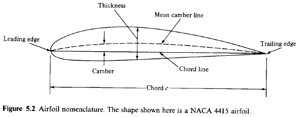
An airfoil’s camber line shape controls the lift it generates. The camber line runs right through the middle of the airfoil, with equal thickness both above and below it. “Camber” is just how curved that line is relative to the chord line, which runs straight from leading edge to trailing edge.
The shape of the camber line and amount of curvature is what impacts lift generation—airfoils with more camber tend to generate more lift. Having more curvature towards the front of the airfoil will cause the front portion to work harder, hence you can get some pretty fine-tuned lift profiles by adjusting your camber line.
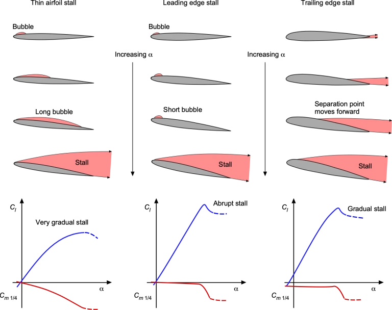
But what we’ve found is that airfoil thickness is what determines where and how the flow separates. A thinner airfoil of around 10-16% thickness will often have a “leading edge stall”, which shows up as a relatively sharp drop-off of lift after reaching some maximum value. Meanwhile, a thicker airfoil will experience a “trailing edge stall”: while its maximum lift coefficient will be smaller than a thinner airfoil, the stall itself is a softer, more gradual drop-off of lift.
We now have two relatively independent ways to control the aerodynamics of our airfoil. Camber determines how much lift we generate at each angle of attack. And the airfoil’s thickness helps control where and when we stall, which is pretty darn useful.
Researching this question also helped me better understand something else. Vortex lattice methods (like AVL) represent a lifting surface as multiple overlaid horseshoe vortices, hence the “lattice” in the name. They apply an airfoil to that lifting surface using only its camber line, not the full airfoil shape.
And now this makes sense! A vortex lattice solver is an entirely inviscid code, but airfoil thickness only controls viscous effects. The VLM solver doesn’t need any information about the airfoil’s thickness. It can’t use it. It just needs the camber line shape to solve the aerodynamics.
From thin to thick airfoils
I love history, so I’m going to share a bit of interesting historical context I found. Thin airfoils were the norm for about the first two decades of aircraft engineering. This is likely due to concerns about thicker airfoils generating more drag, which makes sense intuitively.
It’s also possible that the testing methods used by those engineering pioneers led to that conclusion. The earliest wind tunnel tests used extremely small models at very low speeds. A wing model of barely two inches in chord, tested at speeds of 30 mph, will have an incredibly low Reynolds number—the ratio of inertial to friction forces is just too small.
Nowadays we know that as Reynolds number increases, airfoil drag actually decreases—but if you haven’t tested at higher speeds, you can’t know that! Early engineers might have directly extrapolated their small-scale tests to their full-scale aircraft and so assumed that thin airfoils were always better.
It was the Göttingen aerodynamics laboratory in Germany that revealed that thicker airfoil sections actually performed better at the scale required for crewed aircraft. A thicker airfoil was thus chosen for the design of the Fokker Dr-I triplane, which became one of the most famous aircraft of World War I (and was flown by the Red Baron, Manfred von Richthofen).
A thicker airfoil was also used for the Fokker D-VII. Its superior performance became so notable that, in the armistice agreement between the Central Powers and Allies at the end of the war, the D-VII was explicitly named as part of the war material to be given to the Allies by Germany. That’s how important the thickness of an airfoil was found to be—and it’s the road that led to the legendary fighters of World War II and beyond.
So, what did we learn from this seemingly simple question?
- Paper airplanes can fly without an airfoil because of Newton’s Third Law: an object held at an angle will deflect moving air downward, and that downward deflection produces an equal and opposite force on that object—i.e., lift.
- The reason we don’t use flat plate airfoils is flow separation: the leading edge’s sharp corners cause the flow to separate at that point at very low angles of attack. This makes them entirely unfit for most real aircraft.
- Adding thickness to the airfoil prevents the flow from separating until much higher angles of attack. Changing the thickness also changes how and where the airfoil first sees flow separation, allowing for more controlled airfoil design and stall progression.
A big thanks to AA for their question—this was a genuinely enlightening dive into aero fundamentals, and working to explain it helped me understand these concepts even better than I did before.
Much of the information used to write this article comes from Fundamentals of Aerodynamics, 5th ed., by John D. Anderson, Jr.