
Too often, “aero tuning” is misunderstood to mean trying to squeeze even better performance or capability out of a UAV design.
Last time, we corrected that definition. I use the term “design refinement” to refer to that quest for improved performance. Instead, tuning refers to the work done to help the autopilot know how to fly the airplane. We adjust the autopilot’s control logic settings to determine how the aircraft will handle changes in command or environment.
Eventually you have to test these controls settings. One way to do so is by physically flying the airplane, which is often expensive and risky. Another way is to adjust the controls settings in a computer simulation environment and see how a digital “twin” of the airplane responds.
And how does the simulation figure out that response? It uses the aerodynamic models we give it.
This is one of the ways us aerodynamics-focused engineers support a team beyond the initial design phase. It’s often overlooked and a little undervalued. That’s why I’m talking about it.
I briefly touched on the three primary models needed for a solid sim environment: the vehicle’s baseline aerodynamics, the effect of control inputs, and the contribution of the propulsion system(s). This week I want to go into a bit more depth about each one, with examples of what they can look like and some important considerations.
I’m not going to explain how to make or structure these models. My intention is to help technical and team leads, and non-aero-specialized engineers, better understand what their controls and aero folks are talking about through the jargon and why all this effort is worth it.
The aerodynamic baseline
The heading says it all: the most important aerodynamic “model” for a controls sim is the baseline aerodynamics. This data set tells the computer how much of each force and moment the aircraft experiences at any given combination of angle of attack (alpha) and angle of sideslip (beta).
Having the relationships of coefficients versus alpha is the most critical, for obvious reasons: you need to know how up or down your aircraft’s nose is pointing relative to the wind in order to find its lift, drag, and pitching moment. Telling the computer the airframe’s maximum attainable lift coefficient is also important. This gets used to determine the slowest possible airspeed, and thus the vehicle’s stall speed.
Adding coefficients across a small range of beta angles isn’t always necessary, but the additional fidelity is ideal since an aircraft will encounter some amount of sideslip in its flight. This accounts for the small bit of additional drag and moments generated by said sideslip.
This baseline aero model can take a few different forms, depending on how complex and detailed your given autopilot sim environment is.
Some sims need only a handful of numbers: for example, you could define your lift curve by providing the lift coefficient slope, the alpha where lift is zero, and the maximum lift coefficient. Those three numbers will provide everything the computer needs to calculate the aircraft’s required airspeed and attitude for a particular weight. Often the stability coefficients (pitch, roll, and yaw) will also be given as derivatives and the computer will do the math as needed.
Other sims can ingest databases of much higher resolution. Most of the sims I’ve worked with use matrices that provide each coefficient across a range of alpha and beta. This is nice because you can include more detailed behavior for each coefficient. Some airfoils will see lift slope decrease past a certain angle of attack, but the lift still keeps increasing without stalling. Simpler modeling methods can’t capture that nuance, but the complex model can.
An important note: a simulation environment specifically uses sets of numbers in either vectors or matrices. Some sims require hard-coded configuration files that include values like maximum CL and the slope of Cm with alpha.
What they don’t do is incorporate raw output from an aerodynamic analysis tool. I’ve come across folks who assume they can somehow have their aero tool directly hooked into the sim environment, so any configuration change is immediately reflected in the sim aerodynamics. Unfortunately, even if this was possible, it would probably take way more effort than it’s worth.
You can use any tool you want to generate the aero data—vortex lattice methods, CFD, even hand calculations—but you have to put it into a format the sim can actually use. Thankfully, though that requires a bit of effort, it’s relatively simple through writing some scripts in MATLAB or Python.
Control surface definitions
If you’re trying to tune an autopilot to fly an airplane, you have to give it something to use to fly. That’s where control surface models come in.
These models are almost always deltas: that is, the differences in coefficients between one case with a deflected control surface and our baseline case with zero deflections. If the baseline model gives us the forces and moments at any combination of angle of attack and sideslip, then the control surface models tell the computer how much of each coefficient is added or removed by a given control deflection. It’s this change in coefficient that determines how the simulated (and eventually real) aircraft responds to the deflection.
Like the baseline aerodynamics, these models can vary in format. The bare minimum is providing the appropriate moment coefficient derivative for each control surface: for example, how much pitching moment coefficient is gained or lost per degree of elevator deflection, or the change in rolling moment per degree of aileron deflection.
A more precise model may provide the change in all six forces and moments, across the range of alpha and beta, for a variety of deflection angles. These models can become complex, but if set up properly the simulation can interpolate to whatever condition and control deflection it needs. Including all six coefficients provides the small increases and decreases in lift and drag that happen with any control deflection and thus makes the sim’s behavior more true to life.
A small but important detail of these models is the sign convention used for deflections. Which way does the surface flip for a positive deflection, and which way for a negative one?
For UAVs, which can have wildly unique configurations, this becomes a far more important conversation than you might think. A typical aircraft—with your standard two ailerons, elevator, and rudder—will typically follow one of two conventions:
- A positive deflection is always either trailing edge up or trailing edge down. Positive rudder is typically trailing edge right (though you can change this if you want to be spicy).
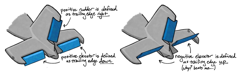
OR
- A positive deflection creates a positive moment, so elevator trailing edge up and rudder trailing edge right are both positive.
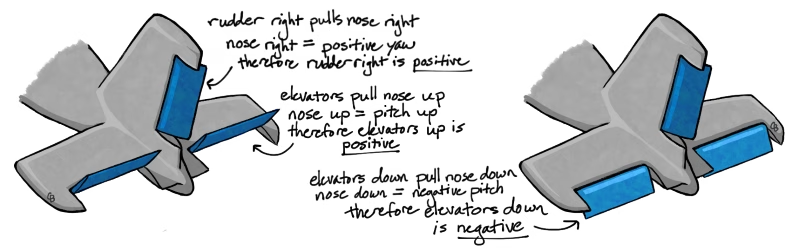
The second convention is often nice because it makes matching deflection data to the actual deflection values easy: positive deflections made positive moments, and vice versa. But what happens when your control surfaces are less conventional?
Maybe you have a V-tail so the same control surface can influence both pitch and yaw. If you decide positive deflections make positive moments, then you get a nose-up pitch from both controls at positive trailing-edge-up positions. But if you try to yaw right, your left tail will still have a “positive” deflection, while your right tail now has a “negative” deflection, despite still creating a positive moment.

In cases like this, I’d default to that first option: set the positive deflection to be either trailing edge up or down (and right or left) for all control surfaces, and the resulting moments will be whatever they’re going to be. Whatever you choose, document your convention and communicate it extremely well to everyone working on the project.
Representing the propulsion
The final piece of a simulation’s needed data package is the contributions to forces and moments from the propulsion systems. Your airplane probably isn’t a pure glider in real life, so it shouldn’t be in the sim either.
At minimum, any propulsion model needs to provide the relationship of throttle to thrust generated by that propulsor. Adding further complexity just improves the sim fidelity: you can account for the torque due to a spinning propeller, or include the roll, pitch, and yaw moments created due to the propulsion vector’s offset from the vehicle’s center of gravity.
These models can actually be much simpler than ones created for performance estimation codes. You only need the final output of the system, i.e., the physics contribution from your actual propeller or jet engine for a throttle command. You might choose to add in a representation of how airspeed and RPM affect your propeller efficiency and therefore your output thrust (I talk about why that matters here) but you don’t need to model aircraft’s fuel consumption or other performance impacts.
The engine’s operation may matter for determining your prop RPM, but that gets baked into your propulsor model. In the controls sim, it doesn’t need its own model.
Why accuracy is (still) negotiable
This is a lot of data to generate and try to get right. The nice thing is that it doesn’t have to be 100% accurate.
If someone isn’t used to working with autopilot simulations, it can be concerning—for good reason—to hear that the sim model doesn’t precisely match the physical aircraft. Wouldn’t the team be tuning for the wrong aircraft design?
Due to how most of these autopilots work, having a bit of error isn’t a major concern.
Like I said last time, most autopilots function off of rates. If a command doesn’t create the corrective action the autopilot is looking for, it will increase the command until either it does get the behavior it’s looking for, or that particular control is maxed out.
Say the autopilot senses a roll to the left from a wind gust and responds by adding right aileron. If the real aircraft’s ailerons generate more rolling moment than in the sim, when the autopilot senses a more intense response than expected it might actually decrease its command to get the desired roll rate. Conversely, if the ailerons on the real aircraft have less control power and generate a smaller rolling moment than expected, the autopilot will command a larger deflection.
This works similarly for every control aboard the aircraft. If the autopilot was tuned assuming the propellers produce less thrust than reality, it’ll just use a lower throttle setting. If the elevators are less powerful than planned, it’ll command larger deflections.
You shouldn’t just disregard model accuracy of course. Having a sim that replicates flight behavior closely is useful for troubleshooting problems with the flight logic. It even opens the door to coding more unique behaviors, like programming the ailerons to deflect trailing-edge-up in transition to slightly reduce lift, increase drag, and slow the aircraft a little bit extra.
But you don’t have to wake up in a cold sweat panicking about sim accuracy. At the end of the day, as long as you’ve given it the best data you have, your airplane can fly itself. It might look a little ugly. It will definitely reveal where you need to improve your models. But it’ll fly just fine, all on its own.